A common question I get is "How do I make my hot Ends"
I will re do the audio - but this is how I turn the nozzles.
http://youtu.be/-G-BW8eLXu4
I'm using machine Tools here.
Safety First !
Saturday, 18 February 2012

Thursday, 12 January 2012
MK2 Hot End kit is now on sale.
After some extensive testing and pre production modles, my MK2 Hot end is now on sale.


The Heater is unchanged.
The heat Shield is now made from 16 MM PEEK rod.
The mount is turned to 14.5mm to fit most of the Wade Extruders.
The Grove is 10mm dia X 3mm wide.

I have incorporated a Unique Tube Clamp.
The PTFE sits over the end of the nozzle and is clamped in place by the PEEK.
Monday, 2 January 2012
ParCan MK2 HotEnd Developmant. Attempt 2 (Good Progress)
After the faults of the first attempt, this design attempts to create a Clamp for the PTFE tube.
I also dislike the idea of having the filament exposed to PEEK.
 Using the lathe I drilled some M6 rod then turned down the end so that I could slide the PTFE tube over it.
As you screw the Brass / Tube into the PEEK, the idea is that the PEEK will clamp the PTFE tube.
I then made a new Brass Tube from M7 brass rod, drilled it 3.2mm for 3mm filament.
The PEEK is 15mm dia and 30mm long, drilled 15mm deep and tapped M7.
The rest of the hole is 5mm dia.

I then screwed up the nozzle so cut the tube down and screwed on one of my standard nozzles.
This is actually mounted on my Mendel at the moment amd prints reasonably well.
The tube interfce works but there is to much Thermal mass to get really nice prints.
I have created 2 more of this design with the nozzle as intended
I also dislike the idea of having the filament exposed to PEEK.
 Using the lathe I drilled some M6 rod then turned down the end so that I could slide the PTFE tube over it.
As you screw the Brass / Tube into the PEEK, the idea is that the PEEK will clamp the PTFE tube.
I then made a new Brass Tube from M7 brass rod, drilled it 3.2mm for 3mm filament.
The PEEK is 15mm dia and 30mm long, drilled 15mm deep and tapped M7.
The rest of the hole is 5mm dia.

I then screwed up the nozzle so cut the tube down and screwed on one of my standard nozzles.
This is actually mounted on my Mendel at the moment amd prints reasonably well.
The tube interfce works but there is to much Thermal mass to get really nice prints.
I have created 2 more of this design with the nozzle as intended
These have been sent them out to some fellow reprappers to evaluate and do a write up.
If all is well, I will have these on sale in Mid januray.
If all is well, I will have these on sale in Mid januray.
ParCan MK2 HotEnd Developmant. Attempt 1 (FAIL)
After making well over 100 of my MK1 HotEnd kits, it's time to update the design.
Inspiration has been taken from my current design as well as the Makergear ideas.
For my first redesign I made a clone of the standard MG Hot end to see how well it worked.
This one was built for 1.75mm filament.
 I will not be selling this design.
The PTFE Tube would ride up inside the PEEK causing the Filament to stick to the PEEK and jam.
After printing for about an hour, it had leaked down the Threads and also at the nozzle joint.


The Top Of the PEEK was later drilled and tapped with a brass insert to stop the tube moving up.
Inspiration has been taken from my current design as well as the Makergear ideas.
For my first redesign I made a clone of the standard MG Hot end to see how well it worked.
This one was built for 1.75mm filament.
 I will not be selling this design.
The PTFE Tube would ride up inside the PEEK causing the Filament to stick to the PEEK and jam.
After printing for about an hour, it had leaked down the Threads and also at the nozzle joint.

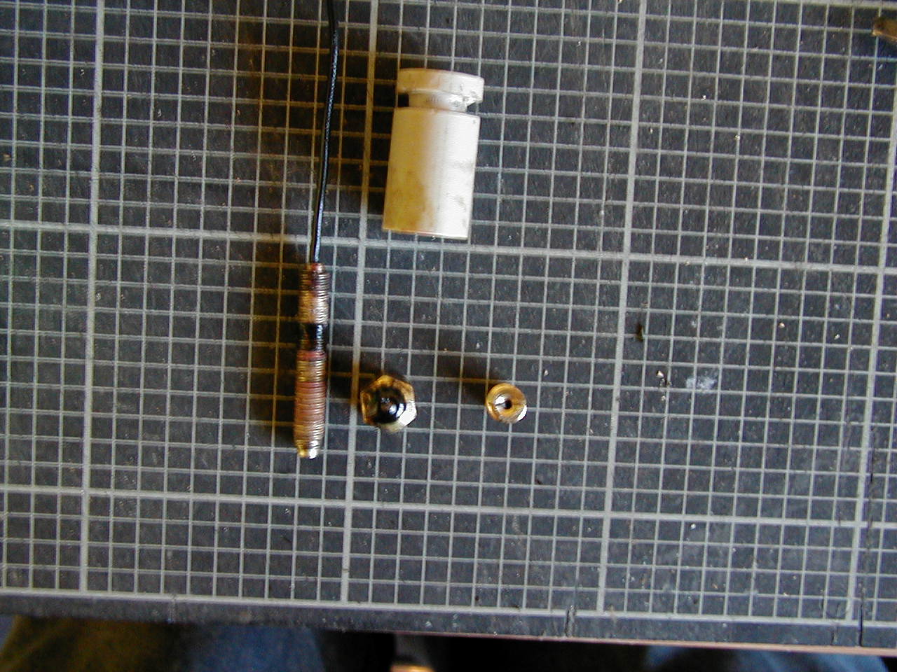
Disassembling the hot End reevealed that it just was not up to scratch, even after several modifications to try and make it work reliably.
I also have issues with trying to make this design work with 3mm filament.
Drilling 3.2mm down M6 threaded rod I can do, but there is very little metal left.
Later designs use M7 Threaded rods.
Parts List:
- 10mm Hex brass Nozzle. 0.5mm hole.
- M6 Threadeded Brass rod drilled 2mm for 1.75 mm filament.
- 15mm dia PEEK Rod, 30mm long. Drilled 15mm deep and tapped M6.
- The tube hole was drilled 3mm to accept 2mm ID PTFE tube.
The Top Of the PEEK was later drilled and tapped with a brass insert to stop the tube moving up.
Saturday, 19 November 2011
Mounting my Hot End
It's come to my attention that a few people have tried to use a Groove mount for my hot ends.
The White PTFE is not structural !
You MUST use the brown PEEK Block to mount and support my Hot End.
I have included a few mounting examples:


The White PTFE is not structural !
You MUST use the brown PEEK Block to mount and support my Hot End.
I have included a few mounting examples:
Using Wades geared extruder

Using Adrians extruder

And the mounting on my huxley.

Wednesday, 27 July 2011
Hybrid Huxley is coming along
I got Motors today. Zapp supplied them as they were in stock.

Note the very tidy work bench :)
 The Patented Belt clamps on the X axis
 You may be able to spot a few odd design issues.....


Note the very tidy work bench :)


Sunday, 24 July 2011
Thermistor table for my thermistors.
Several people have asked me for this so here goes.
// /usr/local/bin/createTemperatureLookup.py --r0=100000 --t0=25 --r1=0 --r2=4700 --beta=4267 --max-adc=1023
// r0: 100000
// t0: 25
// r1: 0
// r2: 4700
// beta: 4267
// max adc: 1023
#define NUMTEMPS 20
short temptable[NUMTEMPS][2] = {
   {1, 713},
   {54, 236},
   {107, 195},
   {160, 172},
   {213, 157},
   {266, 144},
   {319, 134},
   {372, 125},
   {425, 117},
   {478, 110},
   {531, 103},
   {584, 96},
   {637, 89},
   {690, 83},
   {743, 75},
   {796, 68},
   {849, 59},
   {902, 48},
   {955, 34},
   {1008, 3}
};
Wednesday, 20 July 2011
My Hot-End design and other details.
It's about time I updated and wrote about this.
In the past I write about various Hot-End failures, so I designed my own hot end which still works and I still use from time to time.
That Hot end works well but is VERY Dribbly, resulting in rather untidy prints.
I put together an updated standard Reprap hot-end :
http://www.reprap.org/wiki/Geared_extruder_nozzle
This also failed. The PTFE split where it screws into the Brass Nozzle.
Several design ideas later I found a combination that prints cleanly and is strong enough.


The Nozzle is unchanged from the standard reprap design.
The PTFE has a shoulder turned onto it at 10.5mm dia X 4 mm long.

The PEEK is drilled to 8mm then 10.5mm approx 6mm deep.

The PTFE sits inside the PEEK block supporting it.

The Heater I make 8 mm thick, rather than 10mm. It's Pictured here with resistor and Thermistor installed.
This has proven a strong and resillient Hot-End.
I have made and sold a good few of these with no complaints.
You will find these hot ends on sale at http://www.emakershop.com

In the past I write about various Hot-End failures, so I designed my own hot end which still works and I still use from time to time.
That Hot end works well but is VERY Dribbly, resulting in rather untidy prints.
I put together an updated standard Reprap hot-end :
http://www.reprap.org/wiki/Geared_extruder_nozzle
This also failed. The PTFE split where it screws into the Brass Nozzle.
Several design ideas later I found a combination that prints cleanly and is strong enough.


The Nozzle is unchanged from the standard reprap design.
The PTFE has a shoulder turned onto it at 10.5mm dia X 4 mm long.

The PEEK is drilled to 8mm then 10.5mm approx 6mm deep.

The PTFE sits inside the PEEK block supporting it.

The Heater I make 8 mm thick, rather than 10mm. It's Pictured here with resistor and Thermistor installed.
This has proven a strong and resillient Hot-End.
I have made and sold a good few of these with no complaints.
You will find these hot ends on sale at http://www.emakershop.com

Wednesday, 26 January 2011


Sunday, 24 October 2010
Heater works very Well.
After getting my machine going, I installed my design of heater.
I built a new connections board for it. - 2 LED's, Resistor and a 4 pin Molex header.
Why 2 LED'S ? - I install em both ways around so 1 is on nomatter which way the heater is connected.
I also had to make a new Z flag as the new heater is longer.
It gets Nozzle temp much quicker than the Block Heaters.
The nozzle is only 2 degrees lower than the heater (According to my IR beam thingy doofah).
The Block heater was 5 degrees C cooler.
It prints well, even after turning up the Extrusion speed.
It stays put, no noticable movement in it.
The M4 screws that keep the PEEK in plase stay Cool.
I really can't see any operational disadvantages here and now, howerver it is not easy to make.
You need a good lathe with a 4 jaw Chuck.
You need to be able to hold and spin a lump of brass 10mm x 20 mm x 35 mm. 50% Off Center.
You also need to hold the whole thing steady enough and fast enough to get the 0.5 mm hole in the end.
I'll get some pictures up either later tonight or tomorrow.
I built a new connections board for it. - 2 LED's, Resistor and a 4 pin Molex header.
Why 2 LED'S ? - I install em both ways around so 1 is on nomatter which way the heater is connected.
I also had to make a new Z flag as the new heater is longer.
It gets Nozzle temp much quicker than the Block Heaters.
The nozzle is only 2 degrees lower than the heater (According to my IR beam thingy doofah).
The Block heater was 5 degrees C cooler.
It prints well, even after turning up the Extrusion speed.
It stays put, no noticable movement in it.
The M4 screws that keep the PEEK in plase stay Cool.
I really can't see any operational disadvantages here and now, howerver it is not easy to make.
You need a good lathe with a 4 jaw Chuck.
You need to be able to hold and spin a lump of brass 10mm x 20 mm x 35 mm. 50% Off Center.
You also need to hold the whole thing steady enough and fast enough to get the 0.5 mm hole in the end.
I'll get some pictures up either later tonight or tomorrow.
Heater: Update 2
Spent the morning completing my new Heater.
I glued, with Fire cement, the thermister into a 1 mm hole, about 3mm deep between the heater and Nozzle. That seems to me to be the most logical place for it.
The whole thing is also encased in kapton Tape so it can't ping out.
The PEEK block needed some thought or I'd never do up the nuts on the bottom, or worst still, transfer all the heat up the M4 rods.
The Heater side nut is recessed into the PEEK with enough space to get a socket on to it.
The resistor wires have been crimped and Insulated and I'm prety much ready to go.
Once i get the machine printig later today (I hope) I can swap over to the new design.
If this works I'll get on and do some propper drawings and maybe even make some more and try out the removable nozzle.
I glued, with Fire cement, the thermister into a 1 mm hole, about 3mm deep between the heater and Nozzle. That seems to me to be the most logical place for it.
The whole thing is also encased in kapton Tape so it can't ping out.
The PEEK block needed some thought or I'd never do up the nuts on the bottom, or worst still, transfer all the heat up the M4 rods.
The Heater side nut is recessed into the PEEK with enough space to get a socket on to it.
The resistor wires have been crimped and Insulated and I'm prety much ready to go.
Once i get the machine printig later today (I hope) I can swap over to the new design.
If this works I'll get on and do some propper drawings and maybe even make some more and try out the removable nozzle.
Saturday, 23 October 2010
Update: New Heater / Extruder Design
Today i have spent most of the afternoon in Terrys Workshop.
I made a new Style heater first. there is a fair old bit of Turning involved in that.
All went to plan and only broke 1 0.5 mm drill.....
I then started work on my own design.
Once the 4 jaw chuck was in place, I hacked off a lump of Brass about 35 mm long.
It Took a while to set it up in the chuck but once it was centered away we went.
Starting with the 13 mm M10 Thread first, then just moving 2 jaws turnd the job around and turned the nozzle. I decided not to do the Removable nozzle. If I need to I can do that by machining this one.
Once the Nozzle was machined, I drilled it to suite my 1.8 mm filament and put the 0.5 mm hole in the end.
Turned it around a second time. Put in the M7 thread for the PTFE in, then the M10 Thread for the peek.
The job was moved sideways 12 mm and the hole for the resistor drilled.
The results i think are really good.


The PEEK I drilled at 8.5 mm and Tapped it to M10.
the Teflon is standard design.
I made a new Style heater first. there is a fair old bit of Turning involved in that.
All went to plan and only broke 1 0.5 mm drill.....
I then started work on my own design.
Once the 4 jaw chuck was in place, I hacked off a lump of Brass about 35 mm long.
It Took a while to set it up in the chuck but once it was centered away we went.
Starting with the 13 mm M10 Thread first, then just moving 2 jaws turnd the job around and turned the nozzle. I decided not to do the Removable nozzle. If I need to I can do that by machining this one.
Once the Nozzle was machined, I drilled it to suite my 1.8 mm filament and put the 0.5 mm hole in the end.
Turned it around a second time. Put in the M7 thread for the PTFE in, then the M10 Thread for the peek.
The job was moved sideways 12 mm and the hole for the resistor drilled.
The results i think are really good.


The PEEK I drilled at 8.5 mm and Tapped it to M10.
the Teflon is standard design.
Sunday, 17 October 2010
Extruder / Heater design
I have been thinking all weekend about how I can improve on my Heater and Nozzle design.
Looking at the current designs HERE I keep thinking that the heat block is the wrong way around.
The resististor needs to run in line with the filament....
It would also be good to have easily interchangable Nozzles.
This is what I have come up with. (I only have MS paint so the drawing is not great).
The PTFE insulator is the same.
Drill and Tap the PEEK insulator to M10 then screw it on to the Heater.
You will need a bit of Brass 10 mm x 20 mm x 30 mm.
Cut the insulator end out with a hacksaw and turn it a lathe with a 4 jaw chuck.
Screw the Heater on to the teflon.
Add the whole thing to your extruder plate.
Make you Nozzle shorter than usual.
Screw in your nozzle to suite. You may need a Brass m6 nut to retain the Nozzle.
You could always turn the nozzle on the other end of the heater if you wished.
I plan to try and make this in the next week or so.
Your comments and ideas are as always welcome.
PTFE End Nozzle end

Looking at the current designs HERE I keep thinking that the heat block is the wrong way around.
The resististor needs to run in line with the filament....
It would also be good to have easily interchangable Nozzles.
This is what I have come up with. (I only have MS paint so the drawing is not great).
The PTFE insulator is the same.
Drill and Tap the PEEK insulator to M10 then screw it on to the Heater.
You will need a bit of Brass 10 mm x 20 mm x 30 mm.
Cut the insulator end out with a hacksaw and turn it a lathe with a 4 jaw chuck.
Screw the Heater on to the teflon.
Add the whole thing to your extruder plate.
Make you Nozzle shorter than usual.
Screw in your nozzle to suite. You may need a Brass m6 nut to retain the Nozzle.
You could always turn the nozzle on the other end of the heater if you wished.
I plan to try and make this in the next week or so.
Your comments and ideas are as always welcome.
PTFE End Nozzle end

Friday, 15 October 2010
Will this work ?
I bought 20 mm doa PTFE so there is plenty of space.
after pushing 2 nozles out of their threads i came up with this idea....

after pushing 2 nozles out of their threads i came up with this idea....

You reccon this will work ?
There is a nut on the Nozzle resessed into the PTFE.
Monday, 11 October 2010
After the Success of yesterday......
I'm now 2 nozles down :(
The first I broke yesterday - it pushed itself out of the PTFE heat shield, but I had just turned up the extruder speed so blamed my stoopid for that.
I also badly gouged the bed so that went in the bin as well. thankfully MDF is cheap :)
Drilled out the Old PFE last night and re glued a new heat shield.
I wound the heater today, new Thermister new everything.
I then started a Print which delaminated again. Similar to yesterday and upped the Temperature before starting again.
 The Tape on the heater was flush with the PTFE Heat shield. It's moved several mm.
Thankfully this Print bed will survive.....
Back to the drawing board........
The first I broke yesterday - it pushed itself out of the PTFE heat shield, but I had just turned up the extruder speed so blamed my stoopid for that.
I also badly gouged the bed so that went in the bin as well. thankfully MDF is cheap :)
Drilled out the Old PFE last night and re glued a new heat shield.
I wound the heater today, new Thermister new everything.
I then started a Print which delaminated again. Similar to yesterday and upped the Temperature before starting again.

Thankfully this Print bed will survive.....

Back to the drawing board........
Sunday, 10 October 2010
First attempts at printing

I Got my electronics on Friday. I went for the Gen 6 Offering from Mendel-Parts.
These boards are Professionally produced to a VERY High Standard.

Install was Plug and Prey, (As I turned the power on for the first time) Nothing did anything nasty and the Magic Smoke stayed contained as it should.
Saturday AM I connected it up to my Lappy and worked out how to set the USB Port in the RepRap Host software, however it flatly refused to play.
RepSnapper was downloaded and the default settings used, but that also refused to do anything usfull either.
I also broke the Extruder, repaird that and then the Heater failed.
Attempted a Print late Saturday evening and the Repsnapper software refused to do anything like waht i was expecting.
Sunday AM I got the copy of RepSnapper from the downloads page at mendel-parts.com. Fired it all up and loaded the "Test Object" file from the RepRap Host software.
 This is what I got after about an hour.
It looks good from the top, Unfortunately the result is in reality far from good enough.

As you can see there is a lot of air in there as well.

On a positive note, the angles are all correct and the sides are Vertical in both directions.
All in all - not to bad for a 1st attempt.
Monday, 4 October 2010
more tweaking....
Spent the past few days going through every Nut, bolt and screw. It's taken me ages but i know everything is done up tight.
Broke a Y axis belt clamp in the process :(. Now reinforced with a bit of steel.
 My Bed is square - I think I went a bit ott on this bit.
The machine is square and the Z axis is Vertical to the bed.

 Also added a Big Red button !
Anyone got A "Panick" sticker to go on it ?
The 2 LED's are Power To the Button and Power to the Electronics. They will also act as a double check on polarity.
Broke a Y axis belt clamp in the process :(. Now reinforced with a bit of steel.

The machine is square and the Z axis is Vertical to the bed.

 Also added a Big Red button !
Anyone got A "Panick" sticker to go on it ?
The 2 LED's are Power To the Button and Power to the Electronics. They will also act as a double check on polarity.

My Electronics are in the post. I may well video and broadcast on u-stream.tv the installation and Power On.
Lets hope the magic smoke stays where it should.....
Sunday, 26 September 2010
More Pictures.....


Images of the Final build.
 My Machine in all it's Glory :)
The Extruder has been modified to cope with the smaller filament.

The back of the machine.
You can see the "Dust covers" over the Motor Spindles.
You can see the "Dust covers" over the Motor Spindles.
 Hot End / extruder.
 2 LED's to indicate the heater is on.
I made a small cable clip to prevent srtess on the motor wires.
 Y Axis drive.
Spot the missing Lock Nut !
Subscribe to:
Posts (Atom)